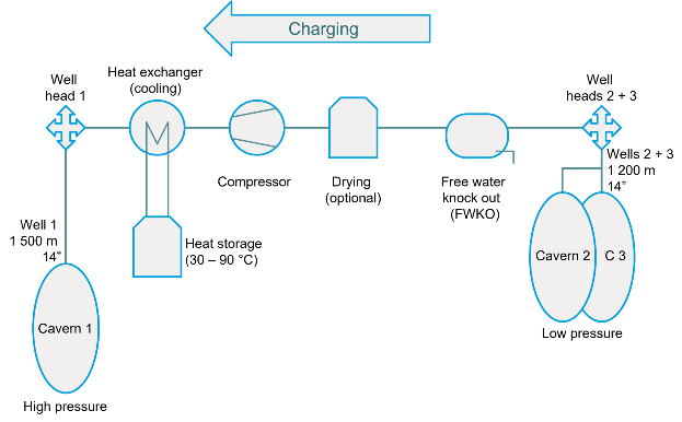
Flow diagram of an erneo compressed air storage for the charging process / electricity storage
The gas or air on the low pressure side would be stored in 2 standard caverns at 100 - 60 bar and would first be passed through a free water separator, because the gas always contains free water remaining in the caverns from the brine process. The water would be separated and the residual moisture removed in a gas drying plant, as necessary. The gas must be dry to avoid causing damage to the system. After compression, the gas is passed through a heat exchanger and the heat is stored in a water reservoir. The compressed air is then stored in a high pressure cavern at 200 - 250 bar.
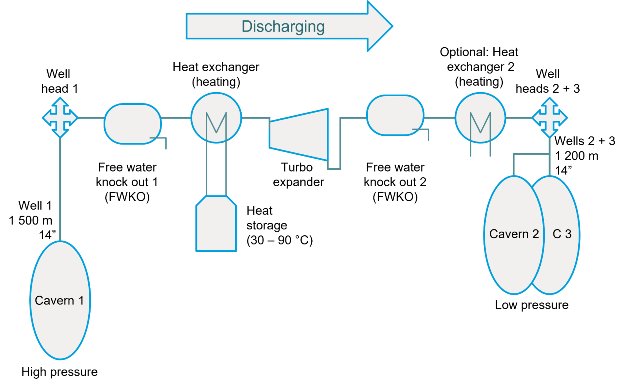
Flow diagram of a new compressed air storage for discharching / electricity production.
In principle, the discharging process is the reverse. The gas is heated in the heat exchanger and then expanded in an expansion turbine, which drives a generator to produce electricity. As the gas cools down in the process, further free water may be produced, which is also separated. Temperatures can drop below 0 °C, depending on the mode of operation. With free water, gas hydrates could form, which would lead to blockages and malfunctions in the plant. Appropriate chemical inhibitors, such as methanol, may also need to be used to prevent hydrate formation. Prior to injection into the low-pressure caverns, the gas can be warmed via an air heat exchanger to prevent excessive stress on the wells.
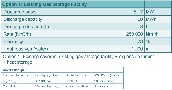
Existing Gas Storage 7 MW - 50 MWh
There are 31 storage facilities in Germany with 272 caverns for storing natural gas. An additional electricity storage facility, albeit small, could be integrated into such existing facilities.
In an existing natural gas storage facility, all plant components for electricity storage are already in place except for the expansion turbine. However, the discharge capacity would be relatively small, since the borehole diameters only allow correspondingly small flow rates. However, it would also be possible to operate several caverns in parallel. The design of such a plant is summarized in the following tables as an example.
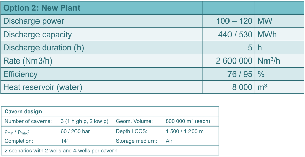
New Storage Plant 100 MW - 500 MWh
A new storage facility to be built could be designed to meet the requirements. Probably, for cost reasons, several caverns would be built and the plant would be designed for a higher capacity than in the following example.
Storage in small surface facilities
The erneo energy storage system is not limited to salt caverns, but can also be built in smaller units, using buried pipes as storage volumes, for example. In the following figures, the withdrawal rate and the stored energy are shown over time for two smaller storage sizes. In these examples, the energy is stored / discharged over five hours and stored / charged during the rest of the day. It can be seen here in particular that the power decreases rapidly. This is due to the fact that the pressures and temperatures are not constant for both the high-pressure storage chamber and the low-pressure storage chamber. It is of course no problem to adjust the discharge capacity by regulating the flow rate.
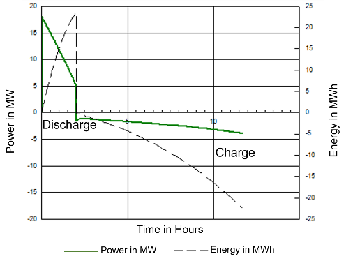
Storage 15 MW with heat storage and 800 / 16000 m3 storage volume
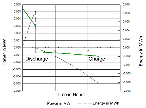
Storage 5 kW / 8 kWh with heat storage and 3 / 6 m3 storage volume